Green Normalmaps.. Question??

Users who are viewing this thread

Yeah you simply discard the blue because the mean difference between the red and green channel will result in the blue channel anyway, this is usually dealt with in the shader during loading, or on the fly if its the unreal engine (or anything else that streams).

z = sqrt( 1 - x*x + y*y );

Warband uses this for all the stationary prop shaders, the ocean shader and the water shader.
It would not be difficult to include the calculation in one of the skinned shaders making xGxR possible for all models.

3Dc is supposed to be interchangeable with xGxR maps but it simply crashes Warband.
 
Yoshiboy said:
Does this mean that DXT5_NM maps must be generated differently to the way normal "blue" tangent space normal maps are generated?

Surely you could, but than you need to write custom pixel shaders that interpret the result accordingly.

As you know, and as Barf said, the usual standard way to interpret the "green" (DXT5_NM) normalmap is:
"read the GreenAlpha texel as a XY components, go from [0,1] to [-1, +1] (by f(k) = k*2-1), then find Z = sqrt( 1 - X*X + Y*Y );"

As Barf said, in this standard case, when you encode the normalmap you must simply discard the Z channel (and encode X Y as Green Alpha).

But if you wanted you could do any other thing, as long as you encode/decode things coherently (encode, when you construct the normalmap--decode, in the pixel shader).

For example, I can think of this alternative decoding procedure, which IMO might make a lot of sense:
"read XY as above, assign Z = 1, renormalize XYZ".
Let's see how does the resulting compression schema performs...

In this case it is like your color points are inside a sided-2 square which does not pass through the equator of the sphere, but is balanced on top of the sphere, touching its north pole. This square is projected over the sphere surface not vertically (as it was before), but toward the origin. Difficult to express in words but I'm sure you can picture that in your mind from the formula. What would the consequence be?

First, you are not wasting that appox 25% of possible Green/Alpha values which in the standard schema correspond to no normals (the ones for which the standard formula results in computing a sqrt of a neg number, i,e. the ones outside the "circle"); this is a plus already. Another plus (or minus, depending on point of view) is that you only get dots in the sphere in the upper part of the sphere, a bit above the equator. In practice, this means that you are gibing up the possibility to store normal directions which differs too much (more than 45 degrees) from the real geometrical normal (the one you would see without normalmap), but in exchange you are concentrating on small variations of the normals, having less artifacts encoding these. You can express less drastic normal changes, but have less compression artifacts there.

Note that, in a sense, the standard DXT5 schema has similar advantages over the DXT1 schema but to a less extreme point: in DXT5_NM, you cannot encode normals differing more than 90 degrees (because always z>0).


But this is not the only possibility. For example, you could "set Z = K, (K constant), then renormalize". The biggest K is used, the more you are concentrating your normals around the pole, meaning that you are allowing smaller and smaller drift from the "real" normals, but you can reduce the artifacts for a surface with mild, smooth variations. For example, with K = sqrt(3) you are concentrating your expressible normals to differ max 30 degrees.

This could be good in some cases. For example say I want to normalmap a shiny hull of a sport car. There the normal variations will be very subtle, but, exactly for that reason, I need to really pay attention as compression artifacts (or even quantization artifacts) are going to look very bad. Then I could use a very large K, like 4.


...The practical problem with all that is that you need to encode the normalmap in custom ways (and decode them accordingly in the shader). The attractive thing which DXT5_NM really offers, IMO, is a stardard way to encode normalmaps, that normalmap producing programs are aware of, and rendering engine are likewise aware of, so they can agree.


The same consideration applies for DXT1 normalmaps (the blue ones). If the program you use to produce them could be sure that the normals will be renormalized after reading, then it could do a better job: when encoding a normal X,Y,Z, it could pick the RGB colors that will results in the vector X',Y',Z' closest to XYZ after normalization (i.e.it would also use vetors bigger or smaller than unit length). See what I mean?

But, I'm not aware of any program outputting normalmaps that uses this optimization. They all just quantize each component of the normals, attempting to store a normal which is already normalized (it won't be, due to quantization and compression artifacts). IMO this is because: (1) they might be a little lazy/want to be fast in compression; (2) they cannot be sure that the shader will actually renormalize normals after reading them from the normalmap; (3) this optimization helps only little when it comes at storing normals around the "north pole", i.e. just where precision is most needed (it would help a bit there too, however)
 
@Barf - Ah of course. That makes a lot of sense.

@mtarini - Again, thanks for the explanation. Very enlightening.

The same consideration applies for DXT1 normalmaps (the blue ones). If the program you use to produce them could be sure that the normals will be renormalized after reading, then it could do a better job: when encoding a normal X,Y,Z, it could pick the RGB colors that will results in the vector X',Y',Z' closest to XYZ after normalization (i.e.it would also use vetors bigger or smaller than unit length). See what I mean?

But, I'm not aware of any program outputting normalmaps that uses this optimization. They all just quantize each component of the normals, attempting to store a normal which is already normalized (it won't be, due to quantization and compression artifacts). IMO this is because: (1) they might be a little lazy/want to be fast in compression; (2) they cannot be sure that the shader will actually renormalize normals after reading them from the normalmap; (3) this optimization helps only little when it comes at storing normals around the "north pole", i.e. just where precision is most needed (it would help a bit there too, however)

This is in fact exactly what they did in cryengine3, but in a slightly different context. It was proving bad to store normalized normals into the G-buffer because as you probably guess this is less than 5% of the total possible normals which can be stored in a float3 value.

They came up with a kind of "best fit" map, which scaled the normal according to what gave it the most accurate compression. It is hard to explain but you should check out the white paper, it is a really good read:

http://www.crytek.com/cryengine/presentations/CryENGINE3-reaching-the-speed-of-light
 
Yeah, it's always interesting to visualize what's possible if only we had a lot more data to play with.  Problem here is very, very straightforward; DDS has been feature-frozen for a long time because GPU manufacturers need stable formats if they're going to deal with on-chip decompression, etc.

The thing about any of the uncompressed flavors of DDS (and for that matter, IIRC, this engine will read BMP; IDK about using it on item skins tho) is that they aren't compressed in VRAM; so they're really RAM-hungry to begin with (loading from disk to cache) then really, really bad for VRAM on the GPU, because they are basically treated like TIFF / BMP.

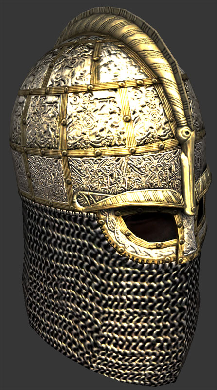
Really, though, this is not a significant problem, if you use the compression tools correctly; most of the artifacts are actually mip problems, in my experience.  If it's set up right, you will not see massive artifacts.  For example, here's a normalmap I built from Dejawolf's Valgard helm (a neato thing I've been wanting to upgrade for quite some time, but only found the time last night):

nord_champion01.jpg
nord_champion02.jpg

In these shots, you're looking at a 1024 diffuse, but only 512s for the normalmap / specular.  I made a very special exception for the diffuse, because the very fine details of the relief work did get bit a fuzzed out at a lower level and I was feeling too lazy to rebuild the uvmap for that area to get it down to 512 and still look about the same.

Here's another example:

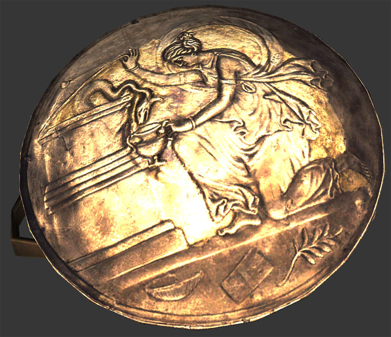
spak_shield.jpg

The original normalmap was very noisy and had a lot of very ugly artifacts.  I really loved the source image used for the diffuse, so I fixed it up by doing a lot of airbrush to push parts of the relief out or in a bit.  It's still fairly flat, without parallax, but it's very reasonable.

Basically, with normalmaps, so long as the diffuse is doing its part, you've modeled enough of the details that it's not being asked to do something it can't, etc. and you've done your compression settings correctly, it's fine.  Where most people have issues is that they don't mess around with the compression settings at all, and at least in the case of the Photoshop plugin, the defaults are fairly horrible.

 
In addition to what mtarini said, some engines all (I'm not sure if M&B does) allow for normals with a magnitude less than one. Usually when taken into account, it lowers the brightness of the light bouncing off.

Also, for those who didn't understand mtarini's description (very enlightening by the way), here's a more general and dumbed down version:

Thanks to pixel shaders, lighting can be evaluated per pixel. One way this can be done is through UV mapping meshes to texture them. As you may know, UV mapping assigns 2D UV coordinates for each face, and since a face is flat, it's quite easy to do. However, a face contains an infinite amount of points inside it's area, but we're limited to the resolution of our texture.

What happens most of the time is that each pixel of the texture file is distributed to specific UV coordinates based on how you UV mapped the mesh. All of the points that aren't covered by a pixel in the texture are interpolated: there values (color for the diffuse, etc) are calculated base on the surround UVs that do correspond to a pixel on the texture.

Let's imagine a single square face as our mesh. Our UV map will be in scale to that face (ie. it's not stretched horizontally or vertically in any weird way). Let's assume that our textures will be 512 by 512. That means the face has 512 uniformly distributed columns and rows, and each intersection of a column and row is a pixel on the texture (remember, our UV map was perfectly to scale with the face; if the UV map wasn't to scale, it wouldn't be uniformly distributed).

For a diffuse texture, the color of each pixel would be placed onto the corresponding spot on the face, and the points that weren't covered would be interpolated; however, for normal maps, this is a bit different. A normal map manipulates the lighting a mace receives at each one of those points.

Each face has a normal. Essentially, a normal is a vector perpendicular to the face, ie. the normal to a perfectly horizontal tabletop would stick straight up. Imagine our face is that tabletop. To keep things simple, imagine we're looking straight down at the tabletop and shining a light straight down at it too. That means the face's normal is pointing straight back at us. Since we're shining the light straight down and the normal points straight up, the light reflected from the face will bounce back straight up.

Before I continue with the lighting, let me say a little more about the normal vector. In most cases, the normal vector is a unit vector. That means it's magnitude is 1. Imagine a hair that is exactly one unit long coming straight out of the center of the face. That's the face's normal. Now, let's say we grabbed this hair by the end, and moved it around. This would change the way the light bounces back from the face.

Now, for the normal map, imagine each one of those intersections I mentioned earlier has one of these hairs, these our our normals. Moving any one of these hairs around changes the way the light bounces back at this intersection completely independent of the other intersections. For the points on the face that aren't covered by an intersection, the normals there are interpolated. (ie, if the hair at point one faces left, and the hair at point 2 faces right, the points in between will start pointing left, then go straight up, and then point right).

How do we tell the graphics card how these's hairs are moved around? M&B has two ways. The blueish normal maps, and the greenish ones (don't they look like lime jello?). For the blueish normal maps, how red a pixel is determines how much a hair is tweaked on the x-axis: medium red is neutral, no red is completely one direction, and pure red is the other direction. Green determines how much the hair is tweaked on the y-axis (with medium green being neutral), and blue determine's how far from the surface of the face the endpoint of the normal is with pure blue being 1 unit and no blue being 0. For these maps, since normals cannot be longer than a unit vector, you're limited to what color combinations you can use. For example, 0,0,1 (RGB from 0 to one) is good, but 1,1,1 is bad.

For the green-alpha normal maps, green determines how much a hair is tweaked horizontally, and alpha determines how much the hair is tweaked vertically. The left over (ie the blue part on the blue normal map) is calculated during run-time. Due to how DDS compresses colors, this is better for large flat surfaces that need very detailed normal maps. Also, like the blueish maps, these are also restricted in what colors you can use for the same reason, you just don't have to worry about a 3rd color, since that part is calculated later.


@mtarini @MadocComadrin

Very enlightening guys. I think it's very nice that you both taken your time to describe how normalmaps works.

MadocComadrin said:
....
Now, for the normal map, imagine each one of those intersections I mentioned earlier has one of these hairs, these our our normals. Moving any one of these hairs around changes the way the light bounces back at this intersection completely independent of the other intersections. For the points on the face that aren't covered by an intersection, the normals there are interpolated. (ie, if the hair at point one faces left, and the hair at point 2 faces right, the points in between will start pointing left, then go straight up, and then point right).
....
So basically speaking, we could say that each pixel of the normalmap represents the type of a "normal-line" on a face. Depending from what angle the light falls on those single lines (normal-pixels) and how the normal map looks like, will determine the light and shadow parts on a face. And that in turn gives us the impression(illusion) that it would be a highpoly model-face.

@xenoargh @all : )
xenoargh said:
...
The only way you could use green normalmaps on non-static objects is to use a custom shader; that requires setting up your mod to use the Warband version of the loader application, and would force end-users to use that to start the mod
...

I am not really familiar with custom shaders, and how to create them. I would be grateful if someone would help me in this regard.
I need a shader with Specular Highlights (like "specular_shader_skin_bump_high") with which I can use green-normalmaps.

And what is the "loader application" ?
Is it like saving the  "custom shader" in to the mod "Resources" folder as .brf file. Making an entry in "module.ini" file and starting the mod?
Does it not work this way?

Here I have compared the standard normalmap with the green one, with different shaders.
As you can see there is a big difference between "standart_shader_skin_bump_nospec_high" and "bump_static".It looks like green normal maps would create more depth. This can of course be also due to the shader.

normalmapcomparison.jpg


Ps: english is not my native language. I hope it was understandable :smile:


Sunnetci_Dede said:
So basically speaking, we could say that each pixel of the normalmap represents the type of a "normal-line" on a face. Depending from what angle the light falls on those single lines (normal-pixels) and how the normal map looks like, will determine the light and shadow parts on a face. And that in turn gives us the impression(illusion) that it would be a highpoly model-face.
Yep, that's pretty much it.
 
Note that bump_static has a very different treatment of light in the scene.  The ambient light is completely different.  That's interesting, I wonder why it was set up like that.
 
Sunnetci_Dede said:
I am not really familiar with custom shaders, and how to create them. I would be grateful if someone would help me in this regard.
I need a shader with Specular Highlights (like "specular_shader_skin_bump_high") with which I can use green-normalmaps.

I sure there are tutorials around, but basically, you need to:

1) write your new shader program, in HLSL programming language
(High Level Shading Language, a part of Direct3D).

HLSL is compiled. You have a source (a file called mb.fx), which is compliled before running the game.
The compilation produces a complied version (a file called mb.fxo, where the warband exe is).
The game loads the complied version. Warband is shipped with it, but without the source.

So, to write your new shader, you need grab the source, modify it by adding your new shader, recompile it to get your modified version of mb.fxo, and overwrite the original mb.fxo.

(this leads to a problem: that the mb.fxo file needed by your mod needs to be not in the folder of that mod, but in the game folder. The application Iron Launcher by [Swyter] can do the overwriting for you and for the users of your mod, so that this is made a lot more seamless for your users).

You won't find the source code of the shader in your Warband directory, but you can grab it from here, thanks to Armagan & team:
http://download2.taleworlds.com/mb_warband_shaders.zip

Naturally this is not the place about how to write shaders in HLSL. You'll find tons of tutorials around. 
But the bit which is relevant here is that a the source file is a collection of alternative "techniques" -- just like a program in, say, C, Pascal or Java, is divided in several "functions" (aka procedures, "subroutines"...). Each technique is identified by its own name (nothing strange: also C functions have their own names).

In HLSL, a technique is usually the union of a Vertex program (what happens to each vertex you send to the card when that technique is active) and a Pixel program (aka fragment shader: what happens for each pixel that is drawn on the screen when that technique is active).

Now, if you want to add a new shader, you need to add a technique to the set of techniques originally present, for example by means of copying and existing one, renaming it, and modifying it.

2) After you changed the shader source code, you need to compile it. This requires to have a directX SDK, so be prepared to install it. Now you have the mb.fxo file.

3) Next step, you need to have a "shader" object in a brf file. This is similar to what happens with textures. As you know, a texture is dds file outside the brf. A BRF file contains a "texture" object, but that is merely a link to the external file (togheter with a few extra info like flags). Similarly, in the BRF file a "shader" object is merely a link to a technique which has to be found in mb.fxo (again, plus a few extra bits like flags -- in this case, the meaning of the flags are totally mysterious, at least to me.
If anbody knows about them, please let me know!). When you added a new technique, you need add a new shader linking to it inside a BRF file, using OpenBRF.

The safest is to take an existing shader (with OpenBRF), duplicate it, rename it, and make it point to your new techinque instead of the technique it pointed at before. You have done it. You can now make your mesh use a material which uses your new shader. End of mini-tutorial.

BEWARE A BUG: at least in M&B 1.011, you can find a problem if your new shader object inside a BRF file. The game will sometimes not load it. The problem goes away if you go windowed mode then full screen mode again. To kill the bug, you need to list your new shader inside the file "core_shaders.brf". Again you have the problem that that file needs be in game CommonRes folder, not your mod folder. So agian, the above menitoned IronLauncher can be your friend.

TESTING YOUR NEW SHADER: in old M&B 0.808, there was a little useful trick to test a new shader without having to reload the game. A key shortcut would just reload the shaders (I think it was ctrl+R but I might remember wrong). Maybe it is me but I cannot find that useful functionality any more.
If anyone knows, please let me know!


Edit: I should mention that you have also an alternative: writing your new shader in ARB shading language instead of HLSL.

ARB is a lower level language for shaders (just like, for example, Assembler is lower level than C or Java). Some might hate it, some will love it.

If you follow this route, you write your new shader in a separate file, e.g. "foo.pp". You don't need to compile it, because what you wrote is already the "assembler of graphic cards". In the BRF file, you need to make your new "shader" object to point at that file, by setting "foo.pp" as the "technique" used by that shader (e.g. in OpenBRF).
 
@mtarini
BIG THANKS for the detailed explanation!

But it is more complicated than I had imagined. Since I created the models for a multiplayer MOD (CRPG), looks as if  the "Iron Launcher" and "custom shader" is not possible option. I can not decide, unfortunately. I think the developers  of the mod will not install them.

But, I've played around a lot and found a better solution with the purple-normalmaps (DXT1 compression).

When I reduce the depth in the "blue channel", or make it perfectly flat(fill the channel completely with white), then these ugly artifacts are no longer visible.
On the other hand, the model gets very shiny in-game. That is why I have held the "Specular Map" darker. But I had a lot of testing in order to come to the ideal values​​.

And now I am satisfied with the outcome. Small file size(DXT1) and no artifacts.:smile:


mtarini said:
.... (again, plus a few extra bits like flags -- in this case, the meaning of the flags are totally mysterious, at least to me.
If anbody knows about them, please let me know!).

The M&B:Warband native normal-map textures almost always use "Flag: 4" and diffuse-maps "Flag: 0" That's the only thing that struck me until now.
 
Back
Top Bottom